- 您现在的位置:买卖IC网 > Sheet目录321 > DM300018 (Microchip Technology)BOARD DEMO DSPICDEM 2
�� �
�
�dsPICDEM� 2� Development� Board� User’s� Guide�
�14.1.8�
�External� Interrupt� Switches�
�Switches� S5� and� S6� can� be� connected� to� the� external� interrupt� pins,� INT0� and� INT1,�
�respectively� on� all� supported� dsPIC30F� devices.� Switches� S5� and� S6� are� connected� to�
�the� dsPIC� DSC� device� through� headers� H6� and� H7,� respectively.� The� signal� lines� are�
�normally� pulled� up� to� +5V� DC� through� 4.7� kOhm� resistors.� Pressing� the� switch� will� short�
�the� line� to� ground.�
�Table� 14-4� lists� the� connections� set� up� by� the� jumper� positions� on� headers� H6� and� H7.�
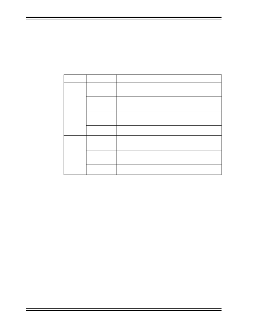
�TABLE� 14-5:�
�EXTERNAL� INTERRUPT� HEADER� SETTINGS�
�Header�
�H6�
�(1)�
�Pin� Position�
�GP� 40�
�Function� (2)�
�Connects� switch� S5� to� Port� pin� RA11of� the� 40-pin� dsPIC30F�
�device� in� general� purpose� socket� U1A1� to� signify� external�
�interrupt� INT0.�
�GP� 28� Connects� switch� S5� to� Port� pin� RF6� of� the� 28-pin� dsPIC30F�
�device� in� general� purpose� socket� U1B1� to� signify� external�
�interrupt� INT0.�
�GP� 18� Connects� switch� S5� to� Port� pin� RB6� of� the� 18-pin� dsPIC30F�
�device� in� general� purpose� socket� U1C1� to� signify� external�
�interrupt� INT0.�
�M� ALL� Connects� switch� S5� to� Port� pin� RE8� of� the� dsPIC30F� device� in�
�either� motor� control� socket� to� signify� external� interrupt� INT0.�
�H7�
�Note� 1:�
�2:�
�GP� 40/28� Connects� switch� S6� to� Port� pin� RD8� of� the� 28� or� 40-pin�
�dsPIC30F� device� in� general� purpose� socket� U1B1� or� U1A1� to�
�signify� external� interrupt� INT1.�
�GP� 18� Connects� switch� S6� to� Port� pin� RD0� of� the� 18-pin� dsPIC30F�
�device� in� general� purpose� socket� U1C1� to� signify� external�
�interrupt� INT1.�
�M� ALL� Connects� switch� S6� to� Port� pin� RD0� of� the� dsPIC30F� device� in�
�either� motor� control� socket� to� signify� external� interrupt� INT0.�
�Header� H6� selects� switch� S5� (INT0).� Header� H7� selects� switch� S6� (INT1).�
�Indicates� the� path� established� when� jumper� is� installed� in� that� position.�
�The� schematic� of� the� pushbutton� switches� and� selection� headers� that� comprise� the�
���14.1.9�
�LED� Indicators�
�Two� LEDs� D3� and� D4� are� provided� on� the� dsPICDEM� 2� Development� Board.� These�
�may� be� useful� in� monitoring� the� status� of� your� application.� The� LEDs,� D3� and� D4,� are�
�connected� to� port� pins,� RB0� and� RB1,� on� the� dsPIC30F� devices,� respectively.� These�
�LEDs� will� illuminate� if� a� high� signal� is� fed� to� them,� but� will� turn� off� on� a� low� signal.�
�Header� H12� is� used� to� connect� the� LEDs,� D3� and� D4,� into� the� circuit.� If� the� jumper� is�
�installed� to� connect� the� GP� pins,� the� LED� is� connected� to� the� General� Purpose� and�
�Sensor� family� device� sockets� (U1A1,� U1B1� and� U1C1).� If� the� jumper� on� H12� is� installed�
�to� connect� the� M� ALL� pins,� the� LED� is� connected� to� the� motor� control� device� sockets�
�(U2A1� and� U2B1).�
���DS51558A-page� 92�
�?� 2005� Microchip� Technology� Inc.�
�发布紧急采购,3分钟左右您将得到回复。
相关PDF资料
DM300019
BOARD DEMO DSPICDEM 80L STARTER
DM300024
KIT DEMO DSPICDEM 1.1
DM330012
KIT USB STARTER FOR DSPIC33E
DM330013
MICROSTICK DSPIC33F/PIC24H BOARD
DNET1
SURGE SUPPRESSOR ETHERNET RJ45
DR-8094
RACK DOUBLE 84"X20.25"X36" BLK
DR-IAC5E
INPUT MODULE AC 5VDC
DRIDC24A
INPUT MODULE DC 34MA 24VDC
相关代理商/技术参数
DM300018
制造商:Microchip Technology Inc 功能描述:DEMO BOARD ((NW))
DM300019
功能描述:开发板和工具包 - PIC / DSPIC dsPICDEM 80L Starter Demo Board RoHS:否 制造商:Microchip Technology 产品:Starter Kits 工具用于评估:chipKIT 核心:Uno32 接口类型: 工作电源电压:
DM300019
制造商:Microchip Technology Inc 功能描述:DEMO BOARD STARTER ((NW))
DM300020
功能描述:开发板和工具包 - PIC / DSPIC dsPICDEM MC1 Motor C RoHS:否 制造商:Microchip Technology 产品:Starter Kits 工具用于评估:chipKIT 核心:Uno32 接口类型: 工作电源电压:
DM300021
功能描述:开发板和工具包 - PIC / DSPIC High V Pwr Module RoHS:否 制造商:Microchip Technology 产品:Starter Kits 工具用于评估:chipKIT 核心:Uno32 接口类型: 工作电源电压:
DM300021
制造商:Microchip Technology Inc 功能描述:MODULE dsPICDEM MC1H 3 PHASE
DM300022
功能描述:开发板和工具包 - PIC / DSPIC Low V Pwr Module RoHS:否 制造商:Microchip Technology 产品:Starter Kits 工具用于评估:chipKIT 核心:Uno32 接口类型: 工作电源电压:
DM300023
功能描述:开发板和工具包 - PIC / DSPIC dsPICDEM SMPS Buck Demo Brd RoHS:否 制造商:Microchip Technology 产品:Starter Kits 工具用于评估:chipKIT 核心:Uno32 接口类型: 工作电源电压: